

Fuel Tank Pickup Modifications-Dmax
The Duramax Fuel sending unit pickup assembly is very restrictive and not designed to provide the large volume of fuel required to support high horsepower numbers. It is relatively easy to improve the flow potential on these vehicles. To start, you will need to remove the fuel tank from the vehicle. You will do well to have the fuel level drawn down to, or below the low fuel light activation level as this makes it much easier to handle. Removal of the tank is not exceptionally difficult. If you have questions regarding details on tank removal I would suggest consulting a Service Manual. You will need the disconnect tools (Image 1) to disconnect the fuel lines.
Pickup-Sender Disassembly
With the tank removed from the truck I recommend washing the top of the unit thoroughly with a highpressure washer prior to disassembly. Cap the nipples to keep water from entering the tank. To begindisassembly, you will need to remove the lock ring (image 2) that retains the sending unit. This ring needsto be turned counterclockwise to release from the cams. The LB7 and LLY have very similar sendingunits with the exception being that the LB7 sender head is plastic and the LLY is Steel.

Image 1
|

Image 2
|
Remove the sending unit assembly from the tank being careful not to drop excessive debris into the tank.With the sending unit/pickup assembly out of the tank, I often to remove the float arm to avoid potentialfor bending. I then pry up the return line (image 3) from the press fit into the lower cup, and then therelease the lock tabs (image 4) from the side of the lower cup and remove the cup.
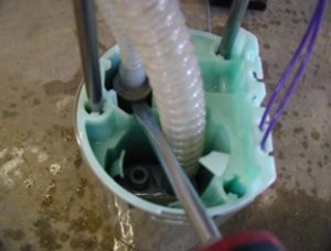
Image 3
|

Image 4
|
With the cup removed, you will now see the OE pickup assy. I first cut the accordion hose (image 5) up atthe head of the sending unit assembly, and then release the tabs (Image 6) retaining the pickup, removeand discard it.
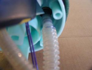
Image 5
|

Image 6
|
Bulkhead Fitting Kit
LLY owners can skip this section and proceed to Pickup-Sender Assembly. The LB7 Plastic sending unithead is also a major restriction. This is why we recommend the Duramax Fuel Tank Bulkhead Fitting Kit.https://www.kennedydiesel.com/detail.cfm?ID=431 To install the bulkhead Fitting kit you must modifythe plastic sending unit head. To start off, you will remove the entire supply nipple and gusset by cuttingwith a cut off tool or similar device. (images 7 and 8) The result will be a round hole flush with thesurface. You will then enlarge this opening in the sender (image 9) to accept the Bulkhead Fitting (Image10) making sure that you locate the hole so that the hex will fit within the area allowed by the recesses andribs of the head. With the bulkhead fitting, I prefer to use a bit of pipe thread sealer (clean thoroughlyfirst) under the external hex to ensure that it cannot leak. You can clean and prime the plastic with a smallamount of clear PVC primer on a Q tip. Proceed with caution as it will soften the plastic up quickly andyou do not want to make mush.

Image 7
|

Image 8
|

Image 9
|

Image 10
|
With the bulkhead fitting in place and secure, you now can add the hose adapt fittings and proceed to theassembly section.
Pickup-Sender Assembly
The Billet pickup and hose assembly is first inserted (image11) and locked into the tabs. At this point thehose length is still excessive and will be cut to length. The bucket may now be re-attached and the returnline can be pressed back into place.

Image 11
|
I now measure the distance from the tank floor to the top of the tank seal (image 10 LH) and note this asmeasurement “X”. It will be approximately 13” but measure to be certain. I then set the sender assemblyup to measure “X” +¼” (image 11 ), line up the hose and cut to length. The reason for the extra length isbecause we want to make sure that the bucket is on the floor of the tank. The OE accordion hose andspring loaded rods make sure of this, but the new hose is rigid and will not move once installed.

Tank Cross Section
Image 12 |

Sending Unit
Image 13 |
The LB7 will use the bulkhead nipple (image 14) with no clamp required, and the LLY will use the largeelbow (image 15) that was previously used for the factory 5/8” vent hose. This connection will require ahose clamp.

Image 14
|

Image 15
|
The Pickup-Sender assembly can now be reinstalled into the tank. Be certain that you have reinstalledthe float arm if removed and that everything is as clean as possible. It should take a slight bit ofcompression to get the ring started. Once locked in, I will attach the hoses prior to re-installing the tank.The LB7 (image 16) uses the Bulkhead fitting for the supply hose and the OEM return is untouched.There is no vent at the sender. The LLY (Image 17) uses the OEM vent nipple for the fuel supply hoseand the vent hose is transferred to the OEM supply nipple. The OEM return is untouched. The supplyhose is left deliberately long to access the lift pump with a safe routing.

Image 16
|

Image 17
|
The tank can now be reinstalled!